Since 2003, I own an O2 XDA I (otherwise known as HTC Wallaby, MDA I, and other brandings). Since 2005, I also own an MDA 3 (HTC Blue Angel, XDA II) with a broken touch screen. To see whether I could exchange the displays (and touchscreens), I took both of them apart. This article describes the innards of the MDA 3, the previous one the XDA I.
As of 2007, my current phone is an XDA Orbit (HTC Artemis, MDA Compact III) with built in GPS.
Special thanks go to the XDA developer forum, which provided me with a lot of startup help for disassembly. For the first part of the disassembly, there was an especially nice photo gallery in the wiki.
You will need a T50(x40) and a T6(x40) torx screwdriver, and a small slotted screwdriver (or better, a plastic equivalent) as tools.
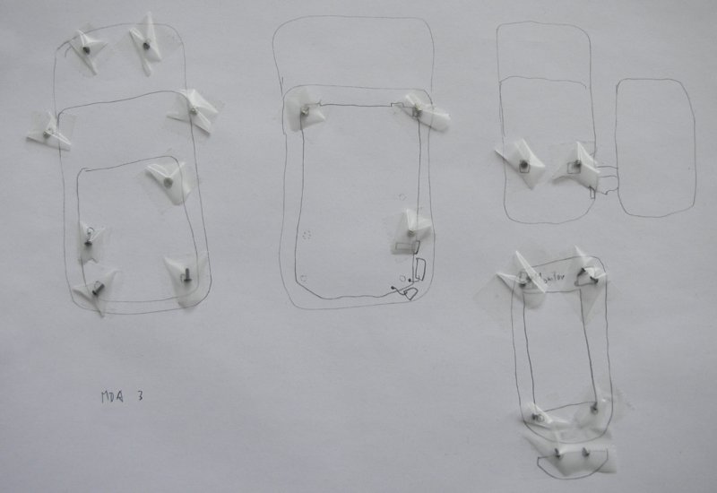
As with the XDA, I made a sketch for the MDA 3 to keep track of the location of screws. It shows the device in various stages, from left to right and then to the bottom. This will become clearer with the photos below.
Again, I taped the screws to their respective locations on the paper so I would not lose them.
The following photo shows the MDA 3 prior to the disassembly. The crack is in the touchscreen, but not in the TFT: The screen displays normally, but input is fragged.
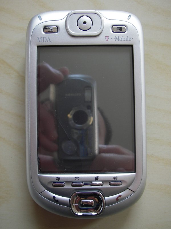
Note: Before opening the phone, remove the stylus, the SIM card and the SD card, as well as all rubber parts on the outside when possible.
Open the keyboard (slide the screen to the top) and turn the MDA 3 around. Remove the battery. Remove the 4 screws under the battery and the two screws on the side (turquoise; not visible on photo) with a Torx 6 screwdriver. The two screws at the back of the screen are a smaller size and I had to remove them with a very small slotted screwdriver.
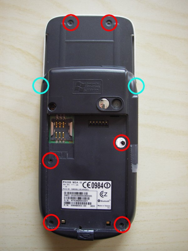
The infrared cover on the right side is taped because it will fall out once the back cover is removed.
Unlike the XDA I, the cover on the MDA 3 is not held by clips. However, in order to not destroy the camera, gently lift from the bottom and remove the black plastic cover.
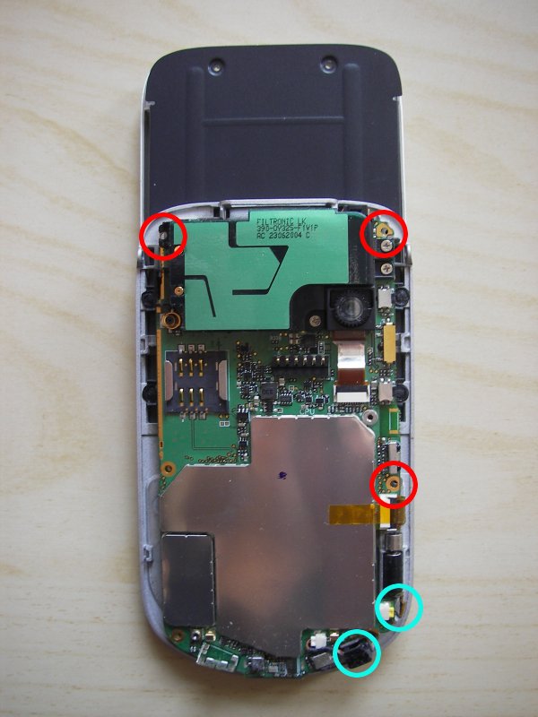
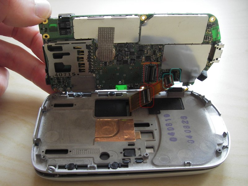
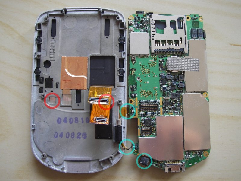
There are 3 more screws to loosen (red). These hold the mainboard to the housing. Aside from the obvious orange tape below the bottom red circle, there are two other connections to the housing (turquoise). The bottom one can be taken out of the housing; I left the other two where they were.
With the mainboard unscrewed, gently lift the board a little from the left side. There are two broad connector cables (TFT and touchpad) from the screen to the mainboard. Take a slotted screwdriver or better, a plastic substitute, and push the connectors down from the mainboard.
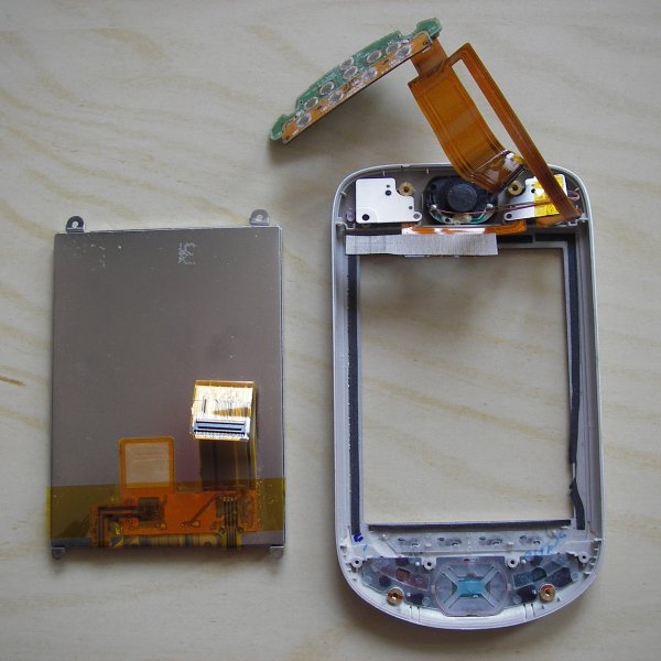
Once the connector cables have been unplugged, open the clamshell entirely to the right. The turquoise circles show where a connection to the mainboard exists (top two) or once was (bottom one).
Now grab the black metal slider below the gray one (left side) and push to the top. We already removed the top two screws of the TFT backside at the beginning; the remaining bottom two screws appear at the place of the red circles once the slider is pushed to the top. Remove them too.
With the slider pushed to the top, now there is enough room for the screen connector cables to slide through. After that, we have successfully separated the TFT section from the mainboard section.
The TFT is held in place be a hideous combination of 6 screws and a connector cable to the bottom which in turn depends on 2 further screws.
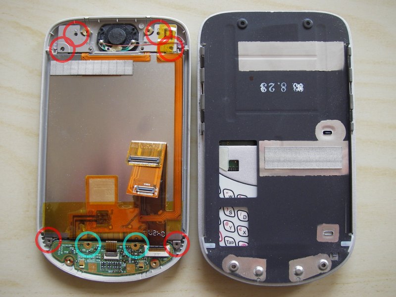
First remove the red circled screws (gently push aside the orange tape at the top right), then the turquoise circled ones. Lift up the screen at the bottom (use a slotted screwdriver on the outer metal mounts circled red) and take out the little board at the bottom (it connects the the 4 soft buttons on the MDA front).
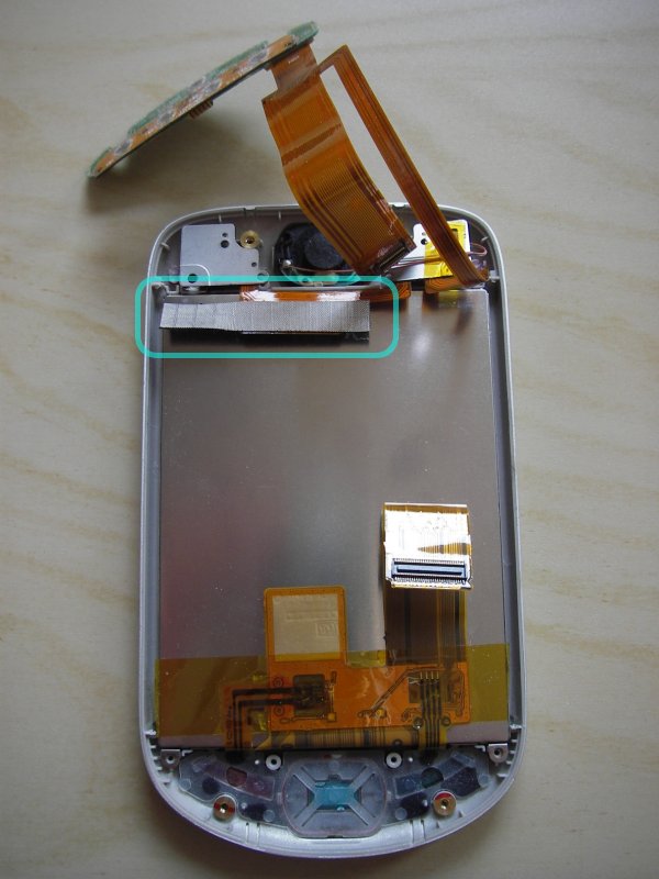
The last remaining thing to do is gently remove the thick tape from the back of the screen unit, and then we can take it out of the shell.
The screen unit, as taken from the shell:
And the screen unit from the front:
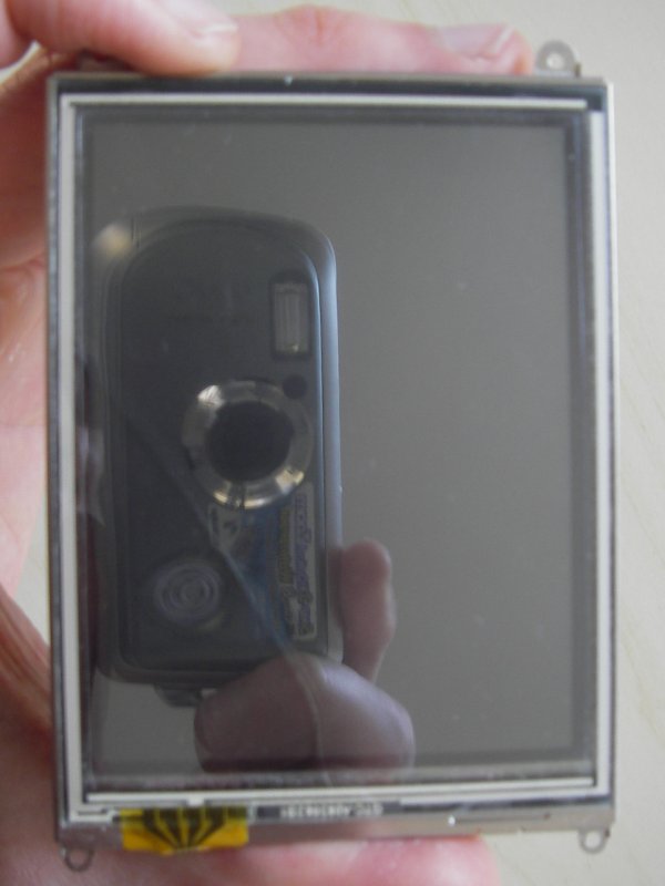
And that was that.
Unfortunately, the TFTs of the XDA I and the MDA 3 appeared to be the same model but had wholly different cabling to their respecive mainboards; this could have been necessary due to the sliding screen of the MDA 3.
As a side effect, I finally got to see into the innards of my Pocket PC devices, which apparently few people do and then document on the web. Therefore, it is my hope that this page may be helpful to someone out there. If you have any questions, please feel free to email me at the address in the header.
Thanks for leaving a part of your attention span here. Have a good day!
EOF (Apr:2007)