FreeCAD is an open source app to build models that you can e.g. 3d print.
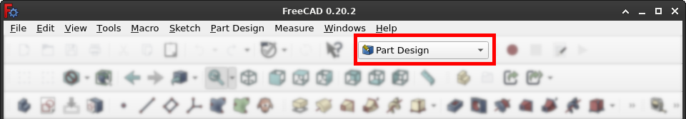
As a beginner in 2024, you will always want the "Part Design" [doc] [tutorial] workbench, which is quite trickily hidden in the toolbars.
Navigating the 3D view [docs] is semi-intuitive:
You can only have one big body that you cut out parts from, so think as a mason, not as a Lego builder. The usual way to start is to draw something in 2d as on paper ("sketch"), then extrude it to 3d ("pad"), then build further shapes that you will subtract from that.
Also: Cool for devs, everything is a Python command [docs], use View→Panels→Python Console to see them in the lower right corner.
So we start with a new sketch in 2d:
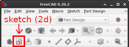
In the 3d view, choose a plane; take YZ plane when in doubt, that will mean you extrude the drawing left-to-right (along x-axis). Now we can choose from a lot of shapes, let's start with a polyline.
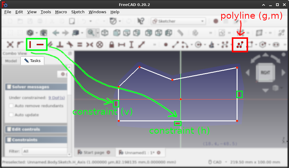
LMB multiple times into the 3d view to create an approximate shape. Also note (a) that FreeCAD tries to guess some vertical (v) and horizontal (h) constraints from the way I clicked, shown in green, and (b) that FreeCAD switched the left pane from "Model" to "Tasks", here the sketching task.
So how do we get to the final 2d shape? Constraints. Found under Sketch→Sketcher constraints they define size/length and orientation of each line in the polyline. Start with the 3 constraints you have.
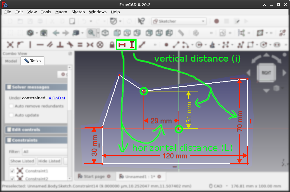
Select the bottom line and press l to edit the horizontal distance e.g. to 120mm, then i to select the left/right lines and edit the vertical distance e.g. to 30 and 70mm. You can select the line either before or after pressing the key (or clicking the appropriate toolbar button).
You can also use l and i to define distances between points, here e.g. between the center point of the coordinate system and the top middle point of the polyline. Notice how in the left pane, the number of "DoF" (degree of freedoms) steadily decreases as we add more constraints. To find out which contraints are missing, wiggle some points and see what moves, then react to that.
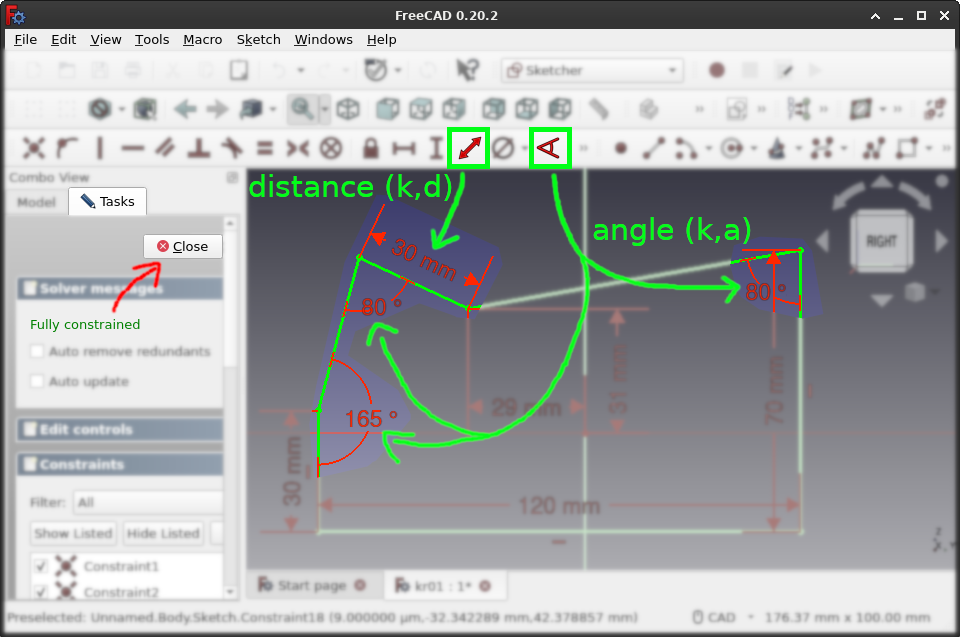
If some angle moves, use k,a on two lines to constrain the angle between these lines; if some point can still wiggle, use k,d to constrain the distance between them, this time not vertically or horizontally but in total.
Once we have 0 DoF left, all the lines turn green, and in the left pane, you can click "Close" to exit the sketch task.
Time to extrude ("pad") our sketch along the x-axis, remembering we did the 2d sketch on the yz-plane.
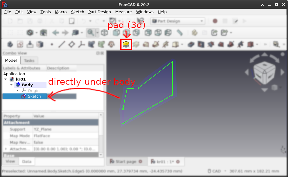
Once again, the pertinent Pad button is hiding in plain sight among the many toolbar buttons. Also note that in the left pane, the body has our sketch as direct child. Now press the "Pad" button (no keyboard shortcut) to get to the task.
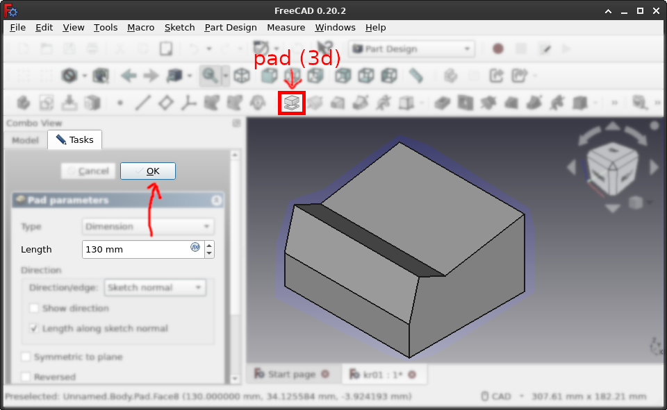
In the (task) left pane, you can define the extrusion as e.g. 130mm, and press "Ok" to exit the task and get to the main view, where the (model) left-pane location of the sketch has changed.
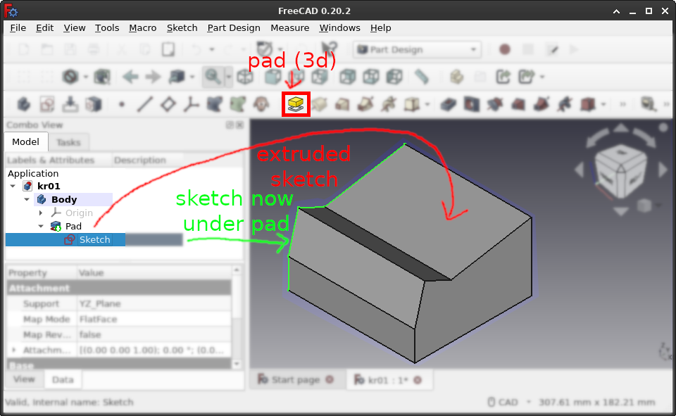
Again in the left pane, the body now has the pad as direct child, which in turn has the sketch as direct child. This is the FreeCAD way of saying "parent depends on child". Also, I pressed Space on the Sketch in the left pane because it was not visible before.
Now lets make some holes.
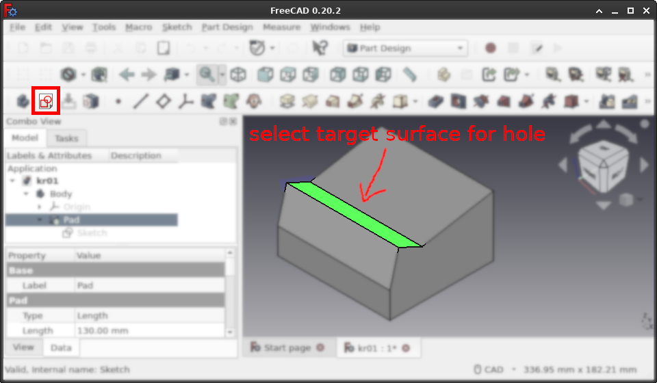
Making holes or cutting away from our main pad follows essentially the same rules as sketch and pad, but with a slight twist:
Our main body was positioned relative to the origin point (0, 0, 0). This time, we want the holes relative to the surface they are in. So select a surface in the 3D view and then press "Create sketch" in the toolbar again.
FreeCAD switches to task mode again, and the toolbars change again, which we use to define our reference frame aka coordinate system.
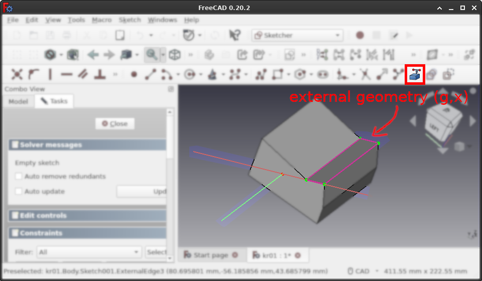
To the right, as one of the last geometries, we have g,x for external geometry. Click it and after that, some lines or points in the 3D view, which should turn purple. Then construct e.g. a circle, and constrain diameter and horizontal and vertical distances relative to the reference frame.
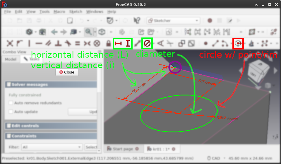
Roughly click the circle and its diameter. Then, start with the diameter constraint e.g. to 20mm on the circular line, and then horizontal i and vertical l distances of e.g. 15mm and 20mm respectively, defined relative to the top left point of the external geometry, and starting at the circle center. Once this is done and the circle fully constrained, click "Close" to end the task and return to the model.
Our latest sketch arrives as "Sketch001" in the left pane, and now we can click "Pocket" in the toolbar.

Just like "pad", choose how deep the pocket goes, then "Ok" the task to return to the model view.
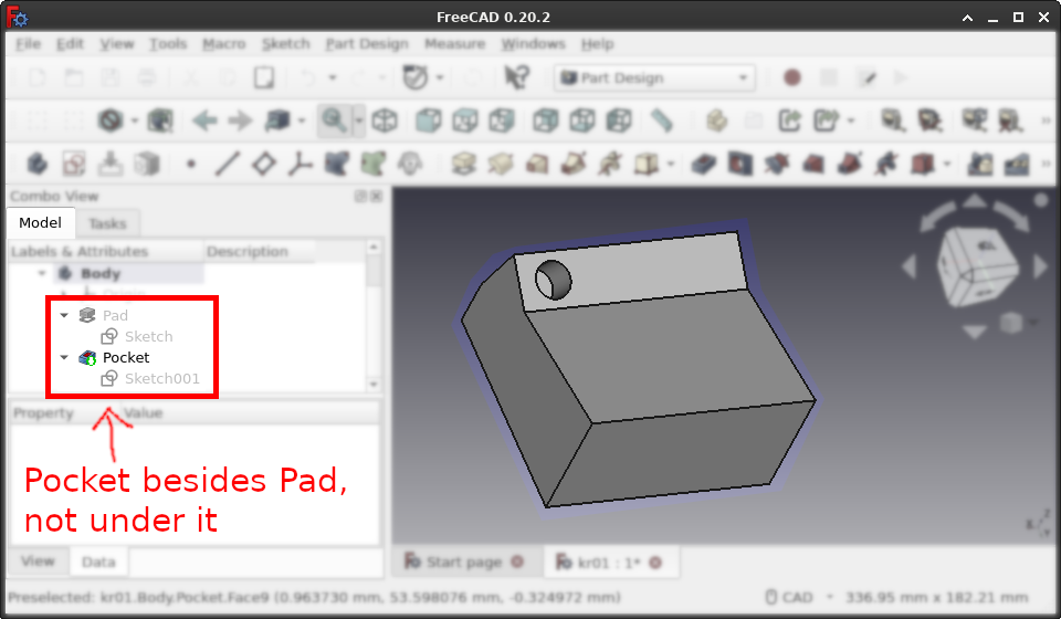
The pocket is visible in 3d, however the left pane is more wonky. Now the pocket resides on the same level ("beside") the pad, while the sketches are children of their respective bodies. This strikes me as somewhat inconsistent, but maybe I am the only one.
You might want to make a lot of similar holes, and that is where the various clone tools come on. One of the simpler ones is the linear pattern, aka repeat along line.
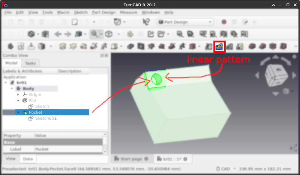
In the left pane, select the pocket you want to repeat and press the "linear pattern" toolbar button, which opens the task.
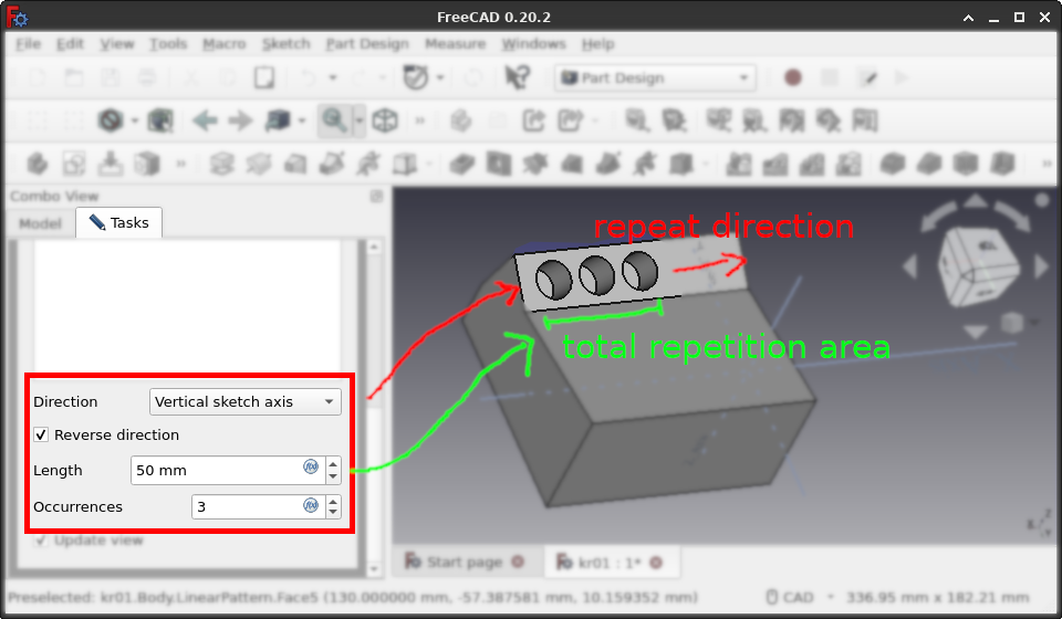
Finding the axis you want can be a bit fiddly, and you need to remember that "length" refers to total area covered, not length between repeats. Together with the number of repetitions which includes the original pocket, we are done here, so press "Ok".
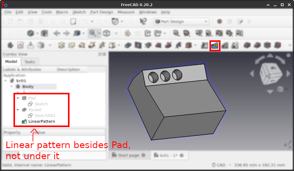
In the left pane, the LinearPattern is on the same level ("beside") the Pad, as is the original Pocket, and only the Sketches are children. So showing dependencies in the tree view is different for 2d sketches and 3d modifiers, apparently.
So far we defined sketches on rectangular surfaces. When they are not, we need a so-called "datum plane", or local coordinate system, to start sketching.
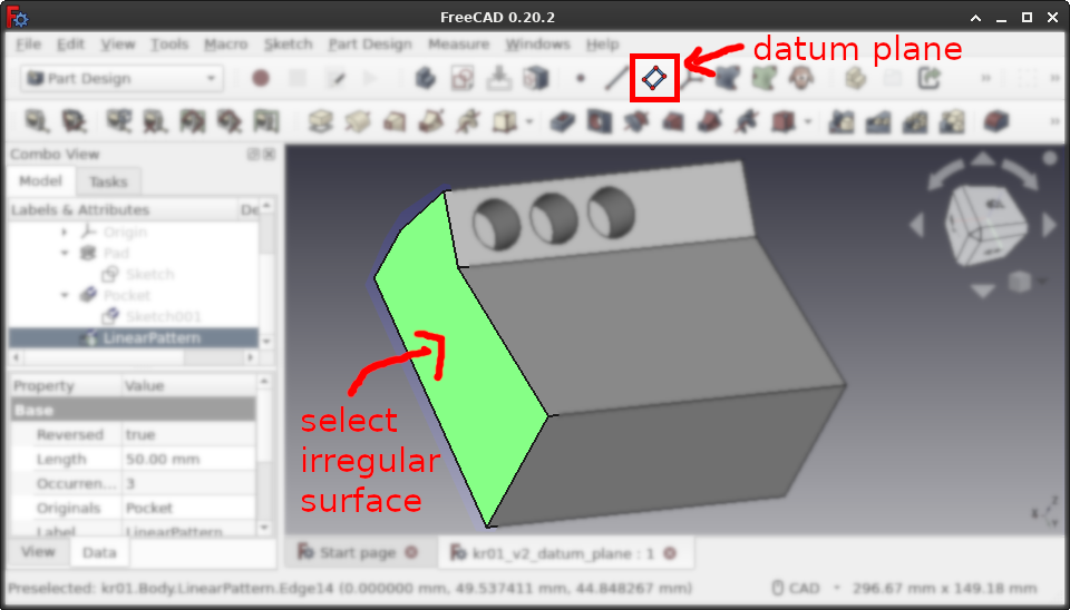
Select your irregular surface or line or point, and create a datum plane, once again hidden somewhere in the toolbar.
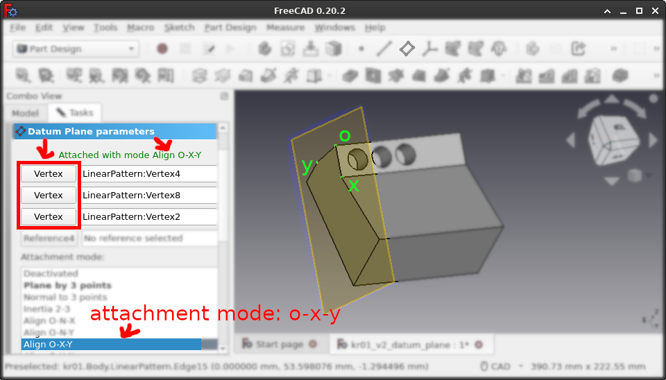
Once again, the FreeCAD default choice is not optimal, here for "attachment mode" which is "Plane"; in particular, what becomes the x/y axis next for the sketch is undefined. So select attachment mode "o-x-y", i.e. origin, x-axis and y-axis, and press each of the "Vertex" buttons in turn to click the appropriate vertex in the 3D view. Notice how the plane in the 3D view turns to support our axes. After clicking "Close" and starting the sketch, you may have to go back and activate checkbox "Flip sides" at the bottom if the sketch turns out to be on the wrong side of the datum plane.
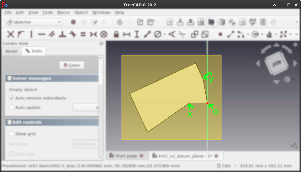
The x-axis is prioritized when x and y vertexes were not orthogonal, looking from the o point. So notice here how the x-axis is exactly as we defined it, while the y-axis is a bit off. Now we can e.g. define a rectangle that is axis-aligned to the plane, which is a lot easier than constraining a slanted rectangle.
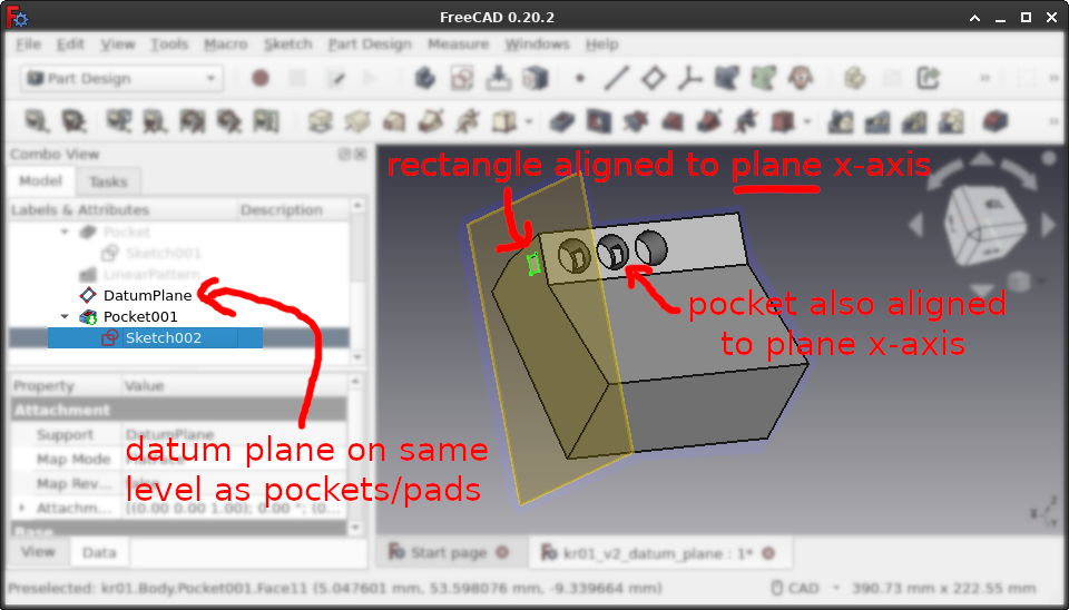
Pocketing such a plane axis-aligned rectangle results in a hole that goes parallel to the top surface. So in such scenarios, it pays to construct a datum plane whose x-axis is parallel to the desired top surface.
Another good use for datum planes is when we want irregular surfaces instead of linear extrusion.
For this we need two sketches. In the current project, we delete everything but the first sketch, planning to copy that sketch and put the second one onto another datum plane. First create the target datum plane. Then use Edit→Duplicate selected object because copy and paste for some reason only puts new objects outside the body, and in the dialog deselect the original plane. Now RMB on the copied sketch in the left pane, and click Attachment editor where you can switch the plane to the target datum plane.
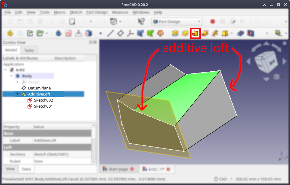
Editing the second sketch to make it somewhat different would make sense here. The number of points can even be different to the first sketch! Then we select the two sketches in the left pane, go to the toolbar and two icons to the right of "Pad", we find "Additive loft" to create an interpolated body, useful for e.g. slants. And finally, we can start making holes again, as usual.
So that was FreeCAD in one little tour! Once you are done with the model, select "Body" in the left pane, go File→Export or Ctrl+E, and then export the CAD to triangles e.g. as STL. And if you are not done yet, there is always the FreeCAD wiki, where you can learn so much more... And that was it! Hope you got a little bit of insight today. Good luck on whatever you are constructing!
EOF (Feb:2024)