3D coordinates should not be hard: [X Y Z] in worldspace projected into [x y z] in one or more cameras sound simple. However, subtle differences between left-hand and right-hand coordinate systems and coordinate normalization make this difficult. In this article, we explore the principal differences between Bundler/VisualSFM, the Matlab Calibration Toolbox, and OpenGL4. The images are assumed to be undistorted (i.e. lens distortion has been removed), so only projective geometry is required.
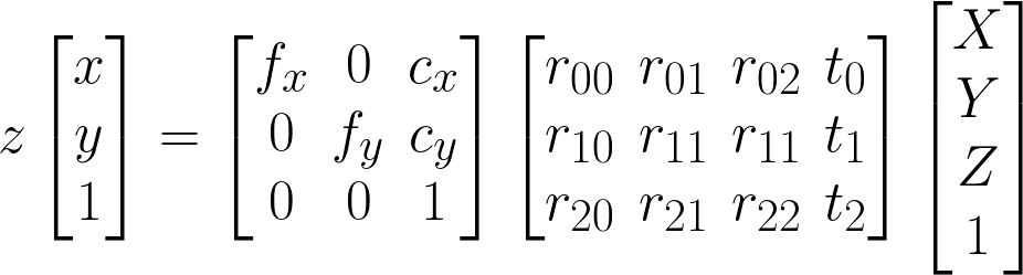
As outlined by OpenCV, camera projection requires a perspective division by z, a 3x3 intrinsic matrix K (sometimes C), and a 3x4 extrinsic matrix Rt put together from a 3x3 rotation matrix R and a translation 3-vector t (not multiplied! Rt is not R·t).
That is, if you have a world space (wld) coordinate [X Y Z] (arbitrary scale, arbitrary orientation), you turn it into a homogeneous coordinate by making it into [X Y Z 1] (if it was not 1, all other components would count as if you multiplied it by that number). To get to the camera stand (sta), you multiply it by the 3x4 matrix Rt (sometimes 4x4 to keep it homogeneous, last row is [0 0 0 1] then). Scale-wise, you are still in world space, but centered to the camera stand, so Rt is your wld2sta matrix. If the camera index is 0, we now have [X0 Y0 Z0 1]. Also note that Rt representing wld2sta implies that within world space, your camera is located at -t and looks in the direction R-1.
The next question: How to get the stand-but-still-world-space view (sta) into your camera view (cam)? The answer involves the focal length f (measured in pixels; sometimes divided into fx and fy for either image axis), the principal point cx/cy (also measured in pixels; usually half the image size per axis), and a perspective division to account for the non-parallel eye rays (we are using a pinhole camera model).
Having the stand (sta) coordinate [X0 Y0 Z0 1], we first have to apply the perspective division, which is a non-linear operation that cannot be expressed in a matrix: [Xc Yc 1 1] = [X0/Z0 Y0/Z0 Z0/Z0 1] is piece-wise dependent on Z0. We are now in parallel coordinates (all on the z=1 plane, in OpenGL: "normalized device space") before proceeding to get into the camera sensor (cam).
Regarding the camera, the principal point c is the middle of your sensor (with slight deviations only to account for manufacturing tolerances), and the focal length f is the "zoominess" of your camera: bigger f means bigger zoom, smaller f means wide-angle. The intrinsic matrix K is made such that the X0 coordinate is multiplied by fx and cx is added to it; analogously Y0 is multiplied by fy and cy is added.
You multiply [Xc Yc 1 1] by K to arrive at the camera sensor (cam) coordinate [x, y, 1], where x goes from 0..wid-1 and y from 0..hei-1. So K is the sta2cam matrix, and Rt is the wld2sta matrix, and the perspective division is in between them.
You can also do the perspective division last, as in the OpenCV formula in Fig.1. In this case, you multiply [X0 Y0 Z0 1] with K and arrive at the cam coordinate [x*z, y*z, z], which after division by z is [x, y, 1], as in the paragraph above. This approach has the advantage that you can multiply Rt (wld2sta) and K (sta2cam) to form wld2cam.
None of the above implies a specific coordinate system: Apart from the axes being orthogonal, every kind of matrix can be used.
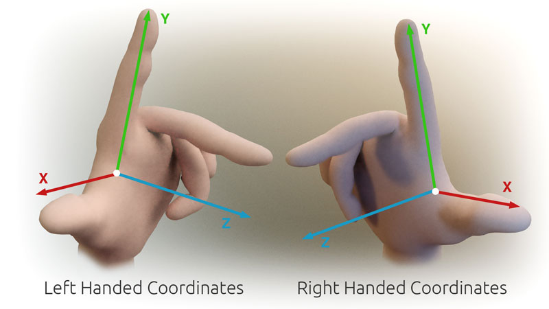
The bundler documentation (same as VisualSFM) reveals that their world space is right-handed: x right, y up, z out of the screen, as in OpenGL (meaning that all depth z values will be negative).
While wld2sta conforms to Rt outlined above, but sta2cam is not handled with a standard K (taken from Bundler documentation, slightly transformed for readability):
P = R * X + t
(conversion from world to stand coordinates, all RHS)
p = P /
-P.z (perspective
division, and switch to LHS)
p' = f * p
(conversion to camera coordinates)
The first line is standard Rt. In the second line, the perspective division diverges by having its z axis reversed. When K is applied, only f is used and cx/cy are completely ignored, meaning that [x y 1] (cam) has the range -wid/2..+wid/2 for x and -hei/2..+hei/2 for y.
The reversal of z indicates that the camera space (cam) used a left-handed coordinate system, given that the world space (wld) is right-handed. Given a matrix Z=diag(1, 1, -1, 1) for z-reversal (also Z==Z-1), the Bundler transformation is thus x=K·Z·Rt·X. To convert from world RHS to world LHS, the final transformation would be x=K·Z·(Rt·Z)·(Z·X).
However, doing a sanity check against CMVS, the matrixes look like this:
| Bundler matrixes | CMVS matrixes |
|---|---|
| T: -0.252282612303 0.0166252150972 -0.0697501066994 | T: -0.252282612303 --0.0166252150972 ++0.0697501066994 |
| R: 0.991884015573 0.0133676511494 -0.126441734156 0.0444352515677 -0.968195746787 0.246218239345 -0.119128767732 -0.24983923494 -0.960932680656 |
R: 0.991884015573 0.0133676511494 -0.126441734156 --0.0444352515677 ++0.968195746787 --0.246218239345 ++0.119128767732 ++0.24983923494 ++0.960932680656 |
Looking at Rt, it seems that both z and y axis have been flipped. So without knowing the exact reasoning, Z=diag(1, -1, -1, 1). Experimental checking confirms the necessity.
Matlab calibration is used e.g. by the Basha 2010 scene flow. The matlab calibration documentation (extrinsics at bottom of page, intrinsics at top) indicates that the chessboard is a right-handed coordinate system (wld) with weird rotation: x out of screen, y right, z up.
Again, wld2sta conforms to Rt, and this time sta2cam follows the perspective division and K (Matlab calls it C) completely:
XX = [X; Y; Z]
(in the grid reference frame, shown
above)
XXc = R * XX +
t (conversion from
world to stand space)
xn = XXc / XXc.z
(perspective division)
xp = K *
xn
(intrinsic
parameters, conversion to camera space)
Lines 1-4 are exactly as described in the "camera projection" section above, so we can assume that the coordinate system is always right-handed.
So if we just pretend that this is a LHS, the scene is entirely mirrored and essentially the same.
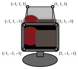
OpenGL uses a left-handed camera coordinate system (cam): x right, y up, z into the screen. As of OpenGL 4, the modelview matrix must ensure that all visible points are between -1..+1 in all 3 axes; then the z axis is flattened during rendering.
In contrast, the world coordinate system (wld) is right-handed: it originated from CAD, where on a sheet of paper, x is right, y up, and z upwards out of the paper. Therefore, in the OpenGL pipeline a z-swap is performed.
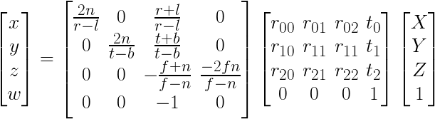
The modelview matrix Rt is the same as in Fig.1, but the intrinsics are wholly different: Since right/left (x), top/bottom (y) and near/far (z) are known and used as "camera parameters", and normalization (on the diagonal) divides by their ranges. The 3rd column simulates a pinhole camera for x/y. Note that the second to last row has negative components to accomplish the z-swap from RHS (wld) to LHS (cam). Perspective division is accomplished by writing z into w, performed by the hardware rasterizer of the graphics card.
Projection (wld2cam) has three steps: Rt, perspective division, and K. Back-projection (cam2wld) has 3 steps in reverse: K-1, perspective multiplication, and Rt-1. Bundler converts RHS (wld) to LHS (cam), just like OpenGL. Matlab world/camera space (wld/cam) is both RHS.
Phew! I still find coordinate transforms tricky, and I hope you found this article useful -- good luck in your camera projection endeavours!
EOF (May:2014)