Microcontroller boards are essentially slow mini computers without an OS, and with a lot of exposed pins that you can put electrical voltage on (OUTPUT), or listen for high or low voltage (INPUT). A popular starting point are Arduino boards, which are open hardware and provide an IDE (integrated development environment).
When buying an Arduino, there are two criteria:
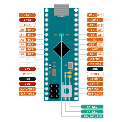
Since I wanted to build a keyboard and not run the board somewhere outdoors, I bought a USB-powered Arduino Micro with 24 pins, visible in the so-called "pin-out":
Pins can be addressed as digital pins "D" (LOW or HIGH), as pseudo-analog pins "~D" (0..255), or as input analog pins "A" (0..1023). GND means "-", and VCC or 3V or 5V mean "+" of the respective voltage, using the engineering (not physics) convention of current flowing from + to -.
But hold on! Before you go buy an Arduino, simulate one first.
The open-source
SimulIDE
[src]
can be installed with apt-get install arduino simulide
on Debian; the arduino package in /usr/bin
[howto]
is used to compile our .ino src files into hex
binaries that the simulator then executes on the virtual
Arduino board.
Or, since the Debian SimulIDE was kind of old,
I installed the 1.0.0 directly from
zip.
Under section "Micro" in the left bar, there is an Arduino Nano which is close enough for our purposes, an LED under "Outputs", a resistor under "Passive" and a probe under "Meters" (a voltmeter would also work, an amperemeter requires re-arranging the circuit).
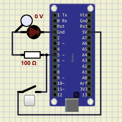
From digital pin D5 (OUTPUT) on the left side, the current flows through the resistor and the LED before going into GND. When the switch to the lower left is pressed, an alternative path starts from 5V on the right side and goes to the start of the resistor, which makes the LED glow indefinitely. Use the latter to confirm with the red "Power" button (in the menu bar on the top) that the LED indeed works.
So the circuit is in the ".sim" file,
and now we add the Arduino program as ".ino" file,
in the panel to the right.
Again in the menu bar, there are gray buttons for "Compile"
and "Upload"; the latter pushes the binary firmware
(.hex) to the microcontroller board.
Arduino files have two functions:
setup() is called once, and loop()
is called repeatedly. State variables are global.
So here we go:
bool ledOn = false;
int t0; // time stamp of last action
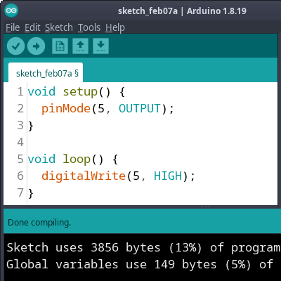
void setup() {
pinMode(5, OUTPUT);
t0 = millis();
}
void loop() {
const int t1 = millis();
const int ts = abs(t1 - t0);
if (ts < 500) {
return; // only act twice a second
}
t0 = t1;
// Blink LED.
ledOn = !ledOn; // on->off, off->on
digitalWrite(5, ledOn ? HIGH : LOW);
}
In setup, we tell pin 5 to be an OUTPUT
(not INPUT) pin. Consequently, in loop we
use digitalWrite (not digitalRead)
to access the pin. While many tutorials use the
delay function to manage time, I prefer to
explicitly use millis time stamps because
parallel activities can be managed better;
note that the absolute value is needed because
at some time the int will overflow and flip.
Notice that pin 5 has a "~" (tilde) beside it? That means we can simulate analog writing 0..255, in truth achieved via PWM (pulse width modulation).
int ledValue = 0;
int ledAdd = +1;
int t0; // time stamp of last action

void setup() {
  pinMode(5, OUTPUT);
  t0 = millis();
}

void loop() {
  const int t1 = millis();
  const int ts = abs(t1 - t0);
  if (ts < 10) { // 10ms between actions
    return;
  }
  t0 = t1;

  // Advance LED.
  ledValue += ledAdd;
  if (ledValue == 0 || ledValue == 255) {
    ledAdd = -ledAdd;
  }
  analogWrite(5, ledValue);
}
Instead of writing just HIGH, we now use a brightness value between 0 and 255, reversing the direction whenever 0 or 255 is reached. Note that the probe will flicker erratically because of the PWM just simulating an analog signal.
Now that we have seen some output, we turn to analog input which uses the "A" input pins in the 0..1023 range. Since SimulIDE does not have real sensors, a sine wave voltage generator will have to do.
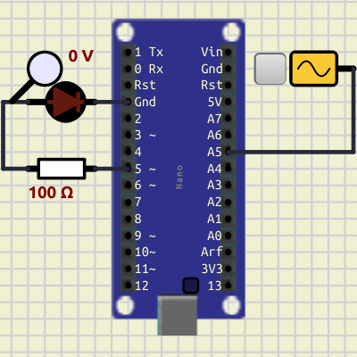
We will use analogRead to get the signal.
This is also a good time to introduce the Serial monitor,
which we start in setup and print to
in loop, noting that it is not as comfortable as
printf.
int t0; // time stamp of last action

void setup() {
  Serial.begin(9600);
  pinMode(5, OUTPUT);
  pinMode(A5, INPUT);
  t0 = millis();
}

void loop() {
  const int t1 = millis();
  const int ts = abs(t1 - t0);
  if (ts < 100) {
    return;
  }
  t0 = t1;

  int inValue = analogRead(A5);
  int ledValue = abs(inValue) % 256;
  analogWrite(5, ledValue);
  Serial.print("A5 at ");
  Serial.print(t0);
  Serial.print(" has input=");
  Serial.println(inValue);
}
We tell A5 to be an INPUT pin, and analogRead
the voltage from it every 100ms, truncating the 0..1023
value to 0..255 before analogWriteing it to the
LED via ~D5.
The block of Serial.print can either take a string
or a number, but not both. You get the monitor by
RMB
on the Arduino board,
then selecting Open serial monitor→USart1
upon which a new window will pop up.
This is also the point in time where you might want to switch to the real Arduino where real sensors are available.
For the real thing, either use the Debian
arduino from apt-get install arduino,
or download a newer version of the
Arduino IDE.
I prefer the "old version" 1.8 because the IDE2 downloads
additional stuff by the gigabyte, apparently.
Under Tools→Board choose the board you have,
for me the Arduino Micro.
Under Tools→Port my choice is /dev/ttyACM0
though that might be different per computer.
Tools→Programmer is irrelevant at first.
Any of the above SimulIDE programs will run on real Arduino hardware too. You will probably want to buy a breadboard, some jumper cables, and a bevy of sensors for temperature, humidity, motion, and distance; I got mine from Funduino [de]. In the Arduino IDE, apart from Ctrl+R for compile, Ctrl+U for upload, and Ctrl+Shit+M for the serial monitor, your experience will not differ much from SimulIDE.
So have fun tinkering, and goodbye for now!
EOF (Feb:2024)